
Extruded Pipe Verification
Reading the printed code on the pipe and checking its diameter as it comes off the extruder, so a bad print or an out-of-tolerance size gets caught on the line, not by the customer.
The challenge
A pipe and conduit extruder prints an identification and sizing code onto its product as it runs. An inkjet head lays the characters onto the pipe at a set interval while it is still moving off the extrusion line. That printed code is how the product is identified downstream, so it has to be there, and it has to be readable.
Two things go wrong. If the inkjet head drifts out of alignment or is set up wrong, the characters smear or fade and the code becomes unreadable, but the line keeps running and keeps shipping. Separately, the pipe's outside diameter can wander out of tolerance as the process drifts. Both are the kind of defect that does not announce itself: the line is fast, an operator cannot read every code or measure every foot of pipe, and the first sign of a problem is often a rejected shipment.
What we built
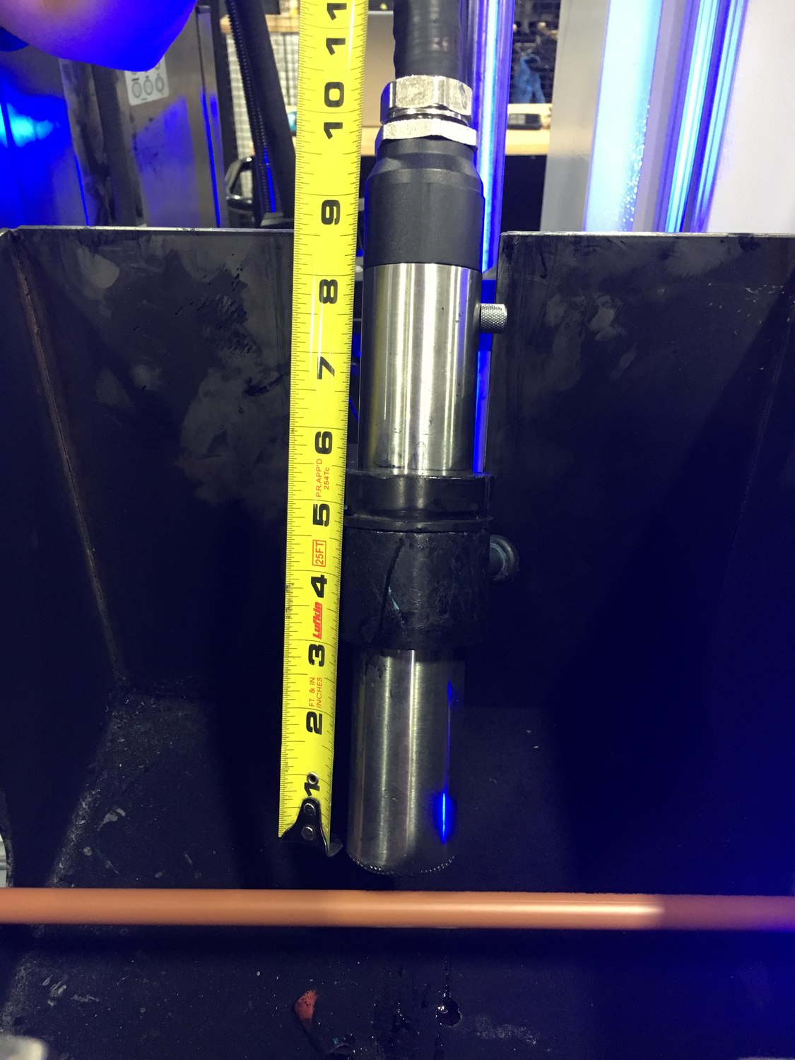
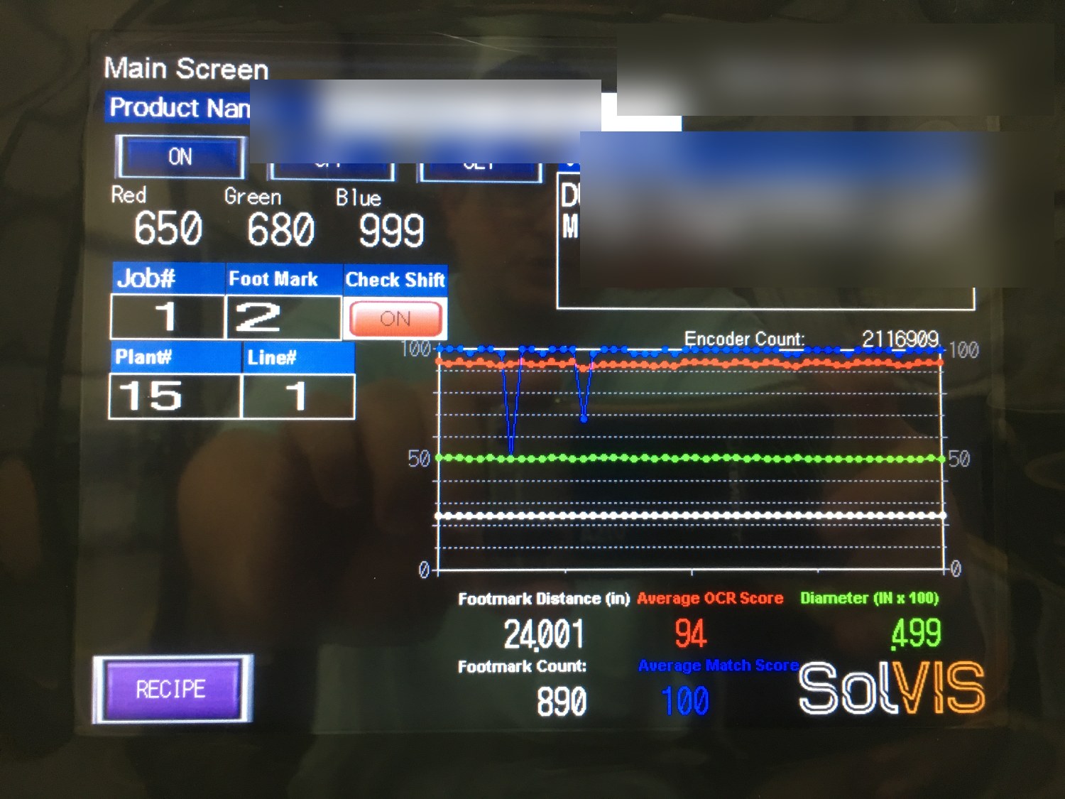
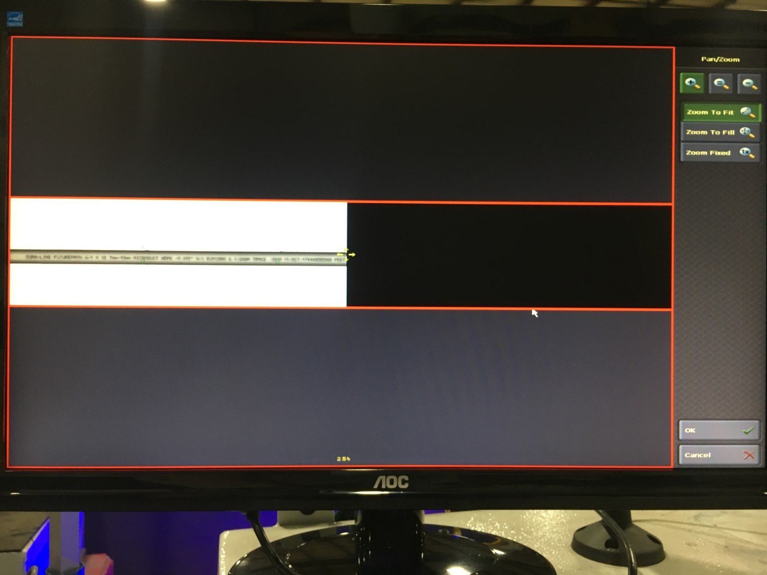
We built a vision system that watches the pipe as it moves. A line-scan camera on a custom optical stack images the surface of the pipe continuously, synchronized to a line encoder, so the printed code is captured cleanly at full production speed without stopping the pipe. As each printed code passes, the system reads the characters and matches them against the expected string for that product, checking both the fixed part of the code and the parts that change from run to run.
In the same pass, the system measures the pipe's outside diameter and compares it to the set nominal and tolerance. So one station answers two questions on every length of pipe: is the printed code correct and readable, and is the pipe the right size.
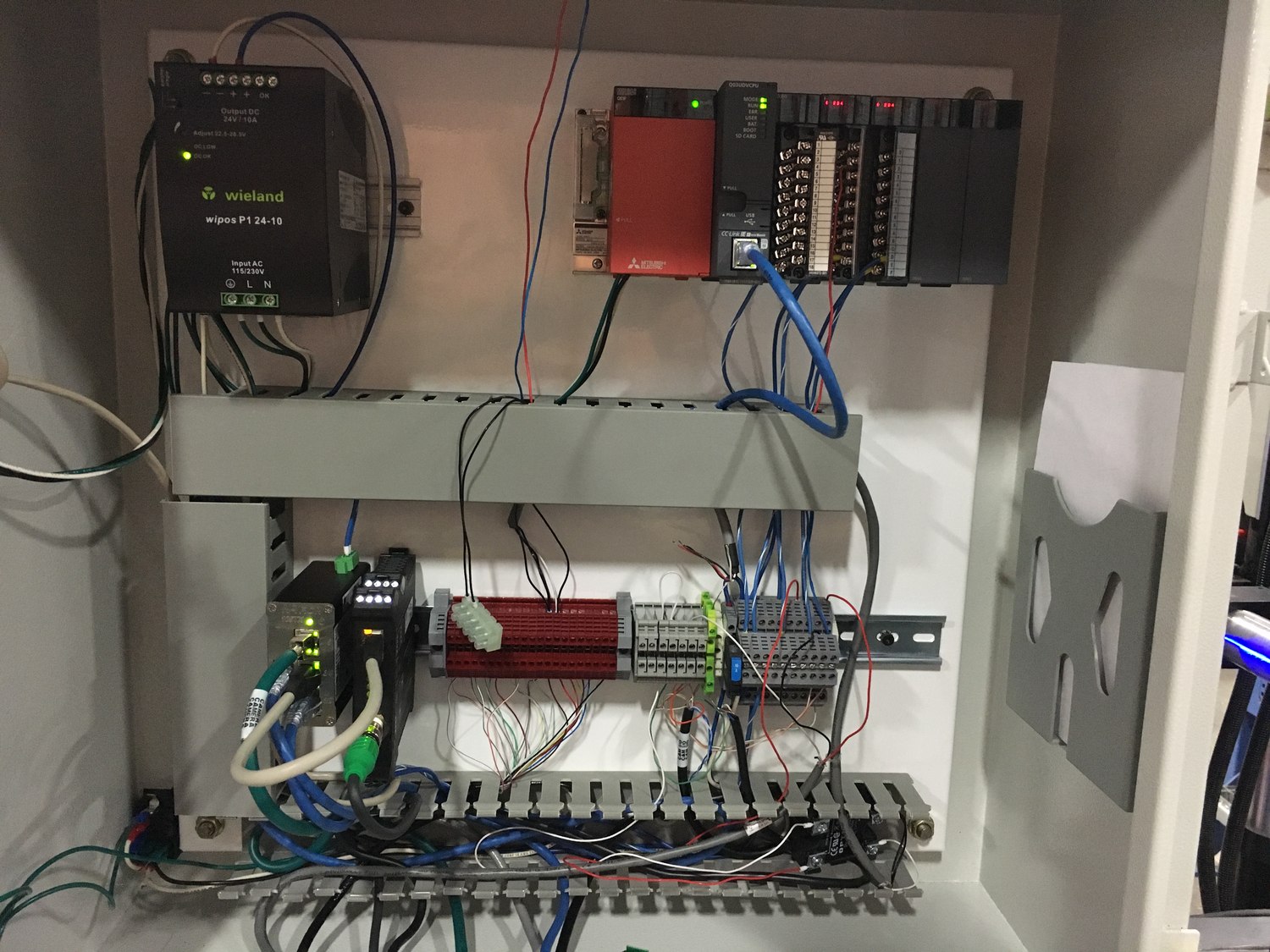
If either check fails, a red stack light comes on at the machine, so the operator knows immediately rather than at the end of a run. The whole thing is recipe-driven through a PLC and HMI: the operator sets the code to match, the color of the pipe, and the expected diameter and tolerance, and switches products without re-teaching the vision. SolVIS designed and built the optical front-end mounting, the electrical enclosure, and the camera, PLC, and HMI programming as one delivered system.
Held to a measurement standard
Reading a code is easy to demo and hard to trust. Because this feeds a quality process, the system was specified to pass a Type 1 gage R&R with a total precision-to-tolerance under 20% at normal production line speed, on controlled samples defined by the plant's quality team. That is the bar a measurement system has to clear to be relied on, not just a good-looking read on a good day.
It was built as a prototype proven on a single production line first, and designed so the same system could be rolled out to the other lines once it was established.
Capabilities used
Machine vision, encoder-synchronized line-scan imaging, OCR and string matching, dimensional measurement, optical and mechanical mounting design, custom UL-style electrical enclosure, and PLC and HMI integration with recipe-driven changeover and stack-light alerting.
On the line
Something running past too fast to check by hand?
Engineer-led, customer-direct, backed by 24/7 support.
(423) 567-3755Talk to an engineer