Steering Rack Inspection
Fourteen assembly checks on every power steering rack, in under ten seconds, with the result written straight into the plant's traceability system.
The challenge
A steering plant builds electric and hydraulic power steering rack assemblies for a wide range of vehicles. A finished rack is a dense assembly: connectors, bushings, clips, bellows, ball joints, boot clamps, breather caps, and a barcode, all of which have to be right. The parts go into safety-critical steering systems, so "mostly right" is not a category.
Those checks were being done by an operator, by eye, on every rack. That is a lot to hold in your head at the end of a line, and the failure modes are subtle. A connector that is seated a couple of millimeters proud looks very much like one that is fully home. A bellows sitting just outside its groove, a spring clip of the wrong type, a bent pin down inside a connector, a cap pressed slightly too high, none of these announce themselves. The plant wanted 100% of assemblies verified automatically, and verified in a way that could be proven afterward.
What we built
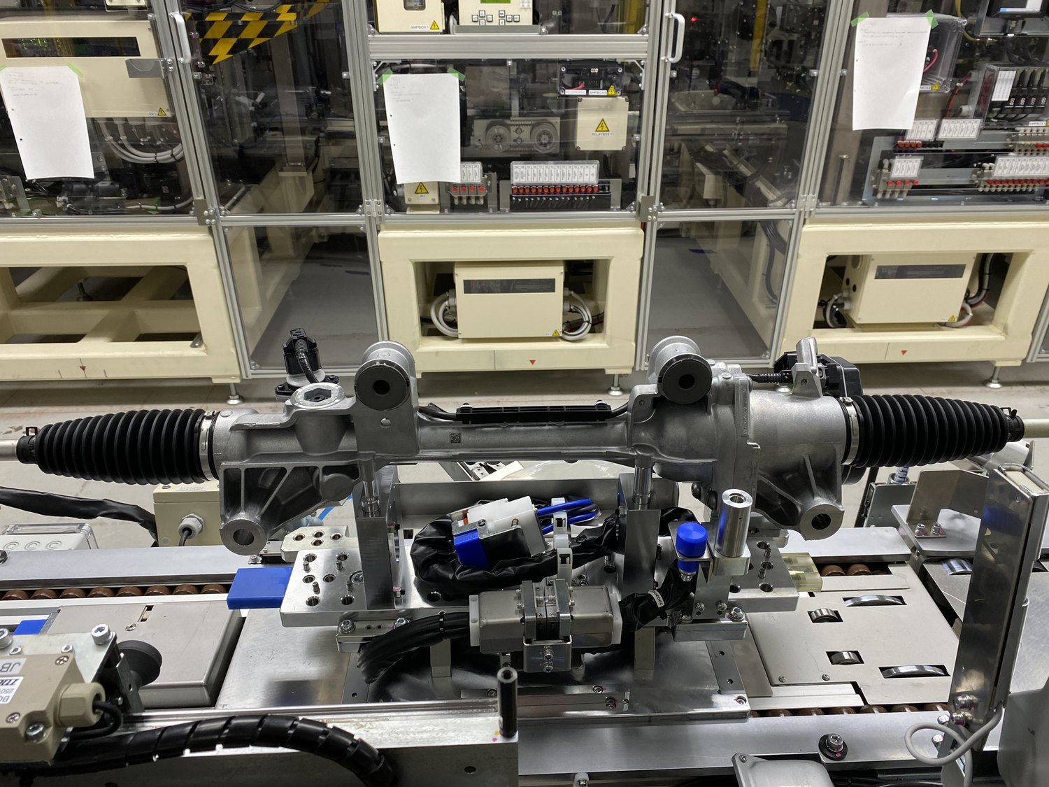
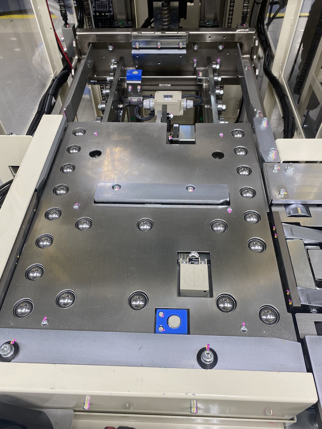
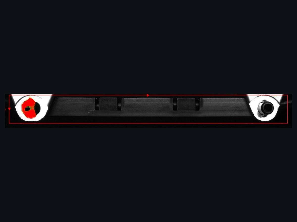
An inspection booth that the rack is rolled into on transfer rollers and held by a locking magnet, so the part sits in a known position and cannot leave until the system has made its call. Twelve camera positions cover the assembly: ten area-scan cameras for presence, type, and position checks, and two profilers where the answer is a height rather than a picture, measuring the yoke plug and the breather cap.
Every camera reports to a central vision controller, an industrial PC with a high-output GPU, which combines the individual results into a single pass or fail for the rack. The operator sees each inspection point on the HMI, so a failure shows exactly which check failed rather than just turning red.
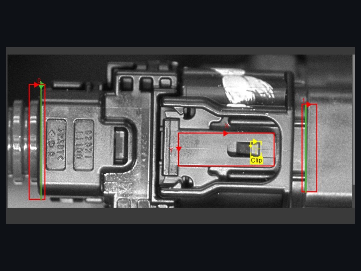
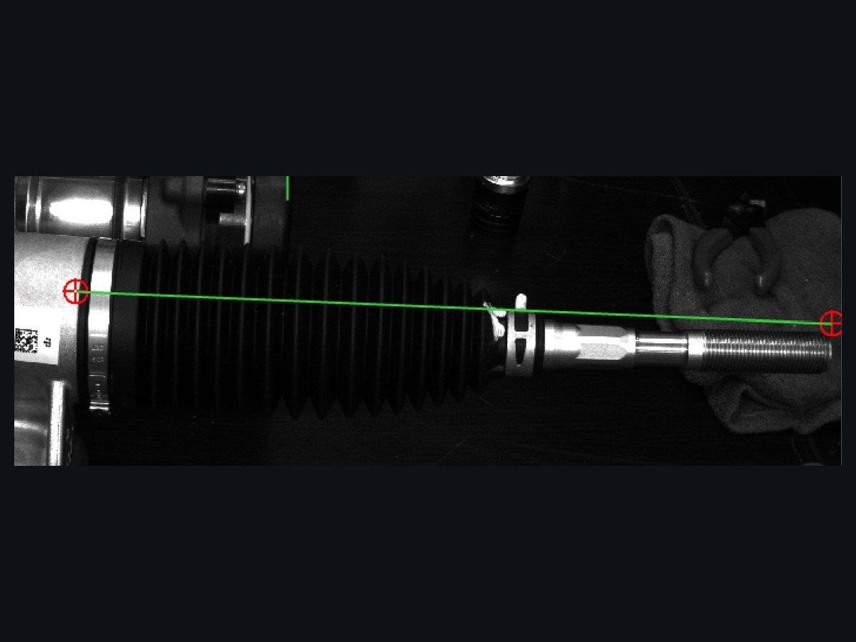
Fourteen checks run inside a ten-second cycle from part entry to result, several of them dimensional: the ECU connector seated within ±2 mm, bushing press height within ±2 mm, bellows in groove within ±2 mm, boot clamp crimped to 6 mm ±1 mm, bent pins measured to ±2 mm from the connector edge, and the yoke plug height held to ±0.3 mm. Alongside those, the system confirms the spring clip type, the correct inner ball joint of two possible types, cable clip seating, bellow slip, an unobstructed hole, and reads the data matrix, returning a print-quality grade with it.
Tied into traceability
The result does not stop at the booth. The vision controller sends the full pass/fail data pack to the plant's existing traceability system over Ethernet, so each rack's inspection record is attached to the rack itself and can be pulled up later.
A failure locks the part out. It cannot simply be waved through, and clearing one requires a supervisory bypass rather than an operator decision at the machine. That is the difference between an inspection system and an inspection suggestion.
Still in service, and still growing
The system was built and validated at SolVIS, then installed and commissioned at the plant with operator training and customer sign-off, backed by a one-year functional warranty against the agreed acceptance criteria. Since then it has been extended to handle an additional part variant, and it is still being supported with spare parts today.
Capabilities used
Machine vision, multi-camera inspection design, 3D profilometry for height measurement, data matrix reading and grading, machine frame design and fabrication, PLC and HMI development, and integration into an existing plant traceability system.
On the line
Too many checks for one pair of eyes?
Engineer-led, customer-direct, backed by 24/7 support.
(423) 567-3755Talk to an engineer